Thermocycler
Let me show you how I have built my own thermocycler machine for PCR reactions in genetics.
The thermal cycler (also known as a thermocycler, PCR machine or DNA amplifier) is a laboratory apparatus most commonly used to amplify segments of DNA via the polymerase chain reaction (PCR). Thermal cyclers may also be used in laboratories to facilitate other temperature-sensitive reactions, including restriction enzyme digestion or rapid diagnostics. The device has a thermal block with holes where tubes holding the reaction mixtures can be inserted. The cycler then raises and lowers the temperature of the block in discrete, pre-programmed steps.
Final result
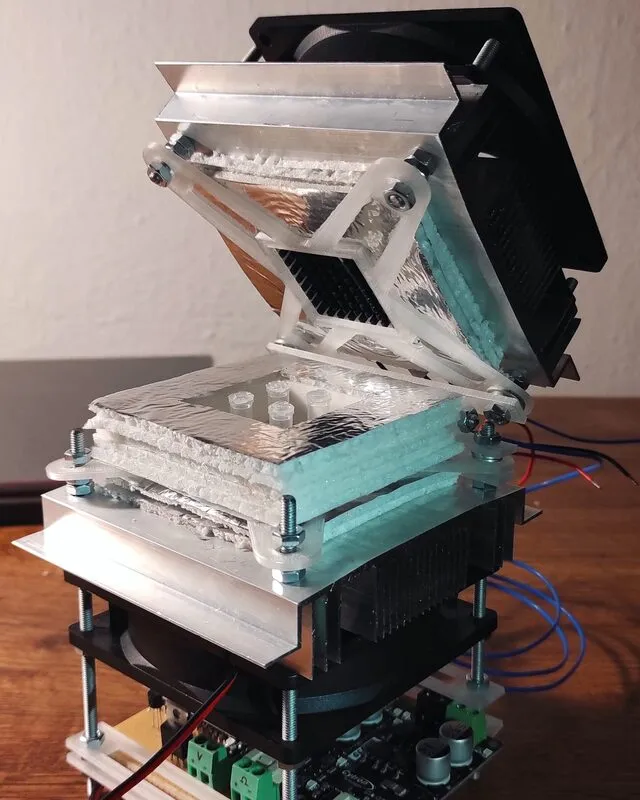
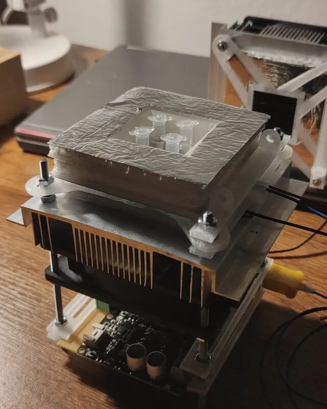
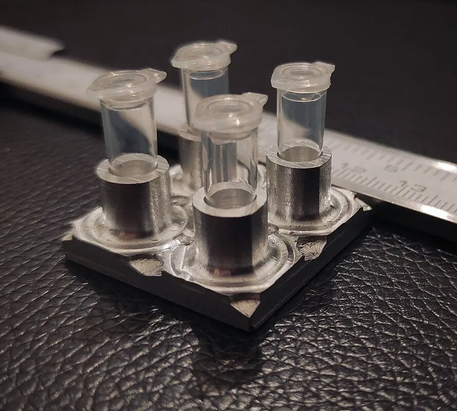
Four standard PCR vials in a heating chamber. Heating & cooling controlled by two TEC Peltier elements with a separate PID loop and custom software.
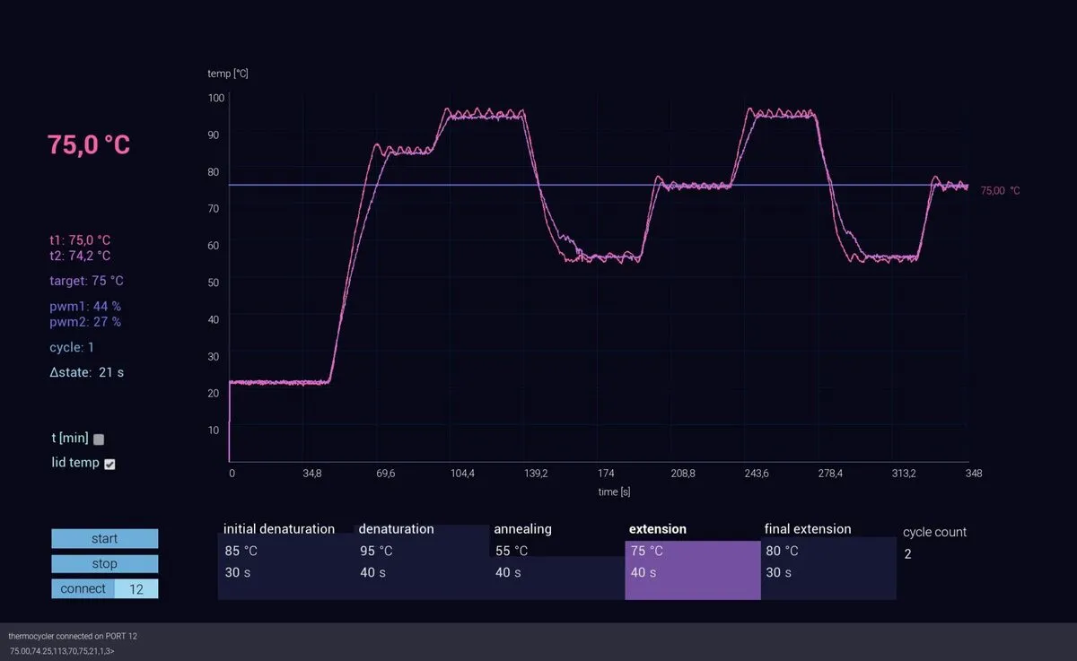 Custom controlling software with logging and history.
Intro
One of the most common processes in genetics is PCR, which is shorthand for polymerase chain reaction.
It is a set of chemical reactions that gives us the possibility to selectively duplicate a specific part of DNA that we extract from a tissue (cell) sample.
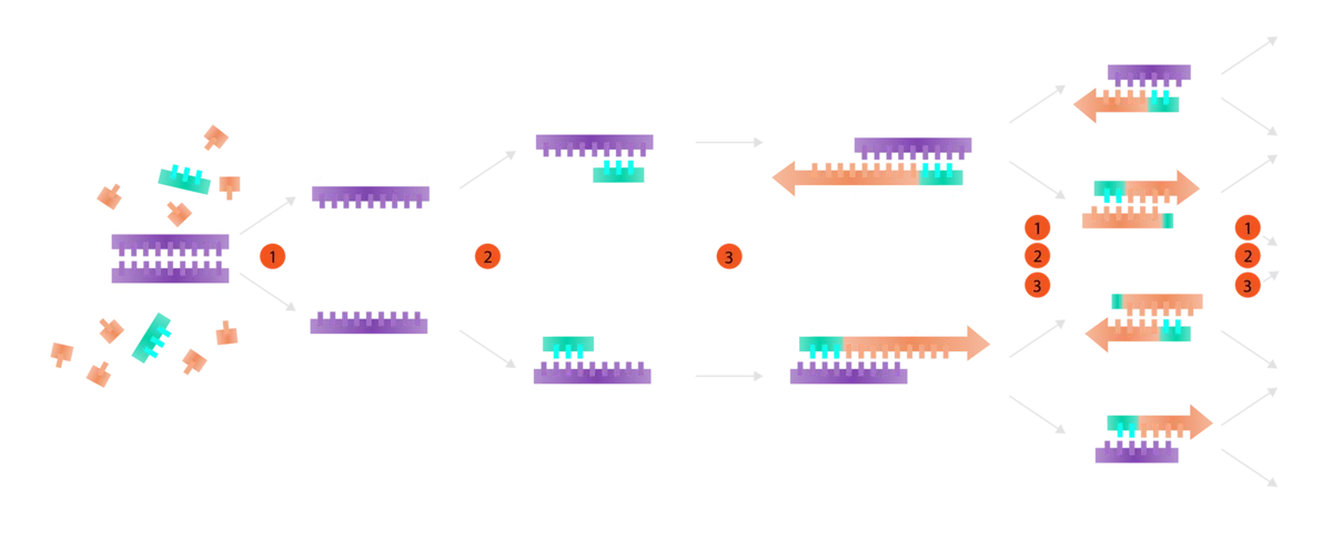
For it to work, it needs a device that controls temperature [C°] in time. [t]
What we want from the machine is to heat the sample as follows:
- 94 C° for 30s (Denaturation)
- 56 C° for 30s (Annealing)
- 72 C° for 40s (Extension)
ΔC°/s, otherwise called ramp-up & ramp-down time, also plays a role. So we will need both heating and cooling.
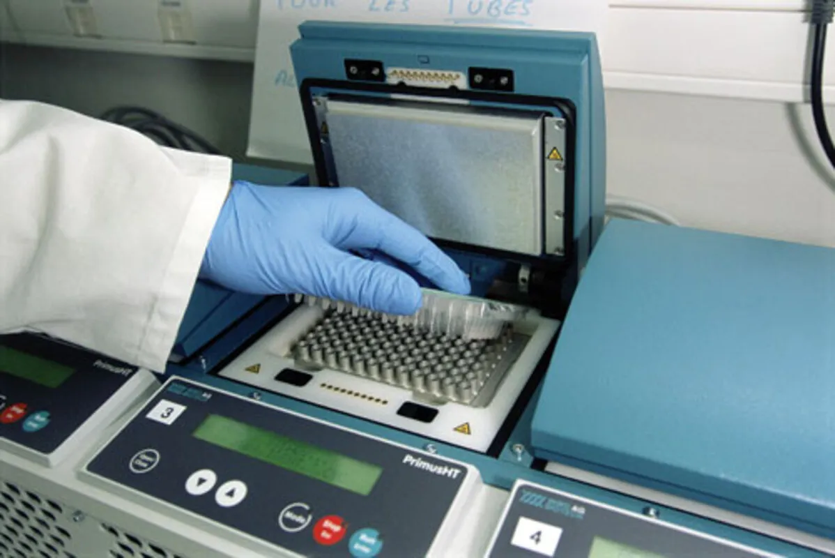
Commercially available units are usually pretty expensive and look like this:
Planning
Usual three stages:
- find diagrams, plans, pdfs of existing commercial products and copy what you can (i.e. do not reinvent the wheel)
- make a breadboard version and measure the performance
- make more robust design
These were probably the two most useful diagrams I have found while browsing and are describing the basic structure of device:
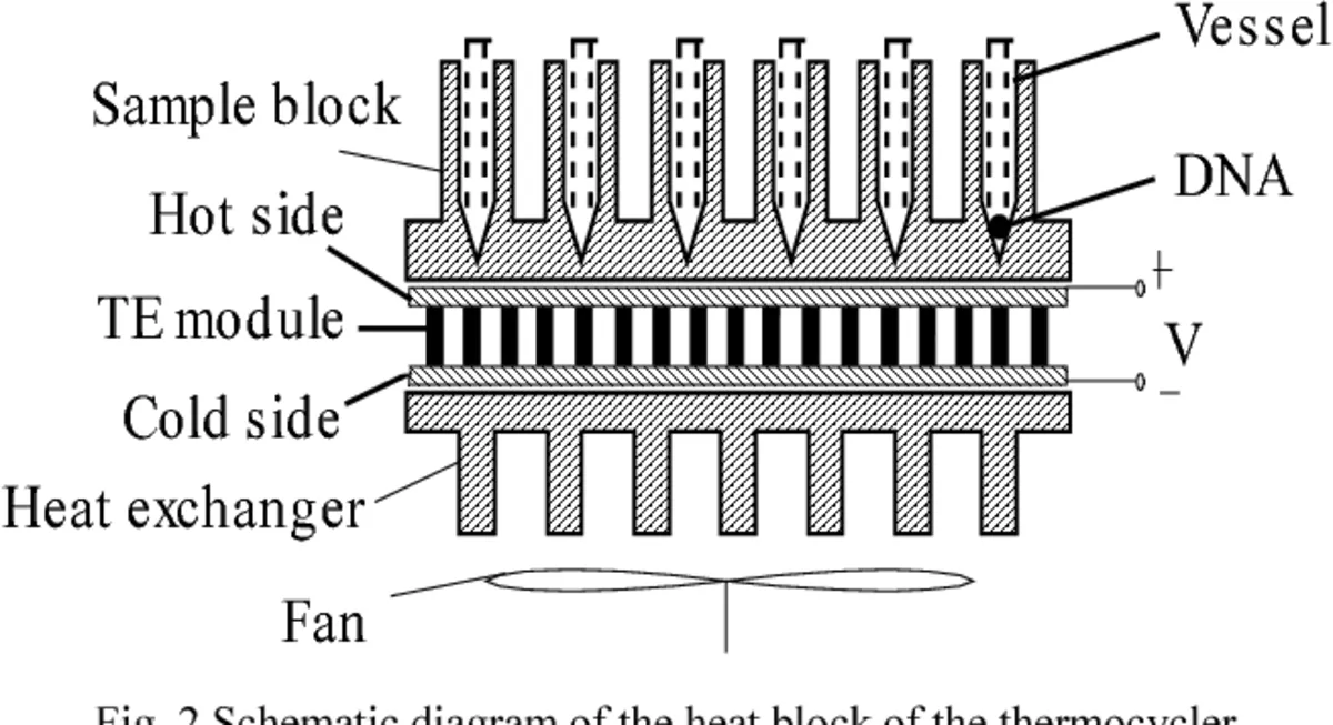
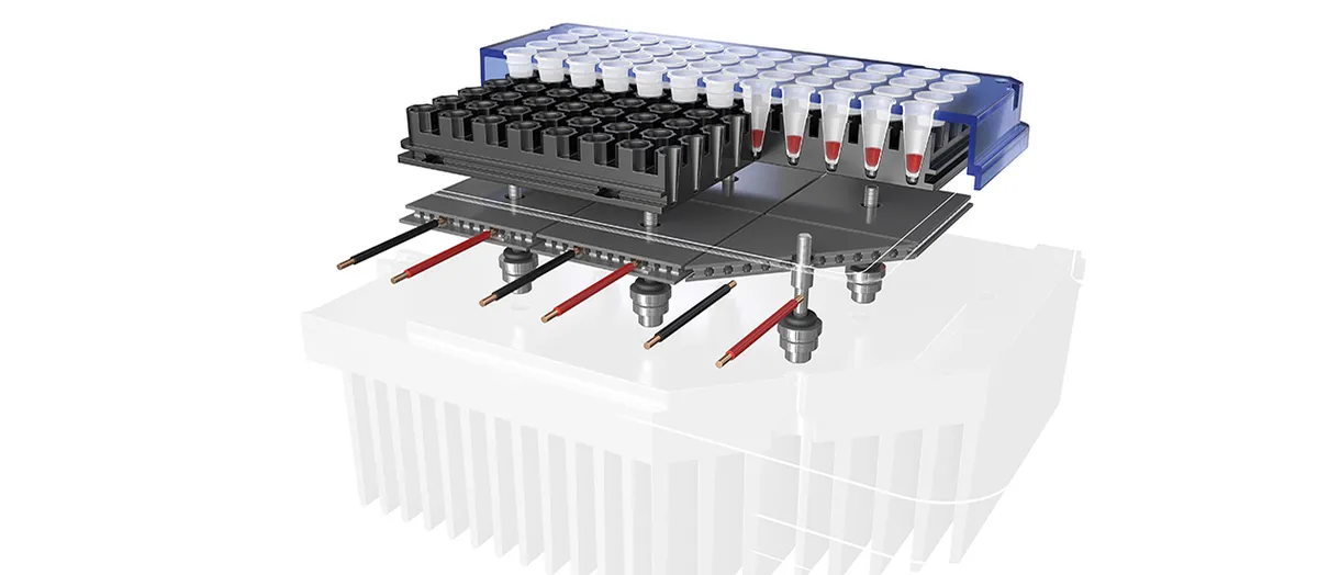
We can see that a primary method for heating and cooling is a Peltier element (TE or TEC in diagrams).
The most complex part seems to be a “sample block”, which needs to be made out of material with great heating conductivity and also needs to have as minimal mass as possible, because more material = heating and cooling takes longer so our ΔC°/s would also increase.
Construction
First I constructed a diagram of whole device:
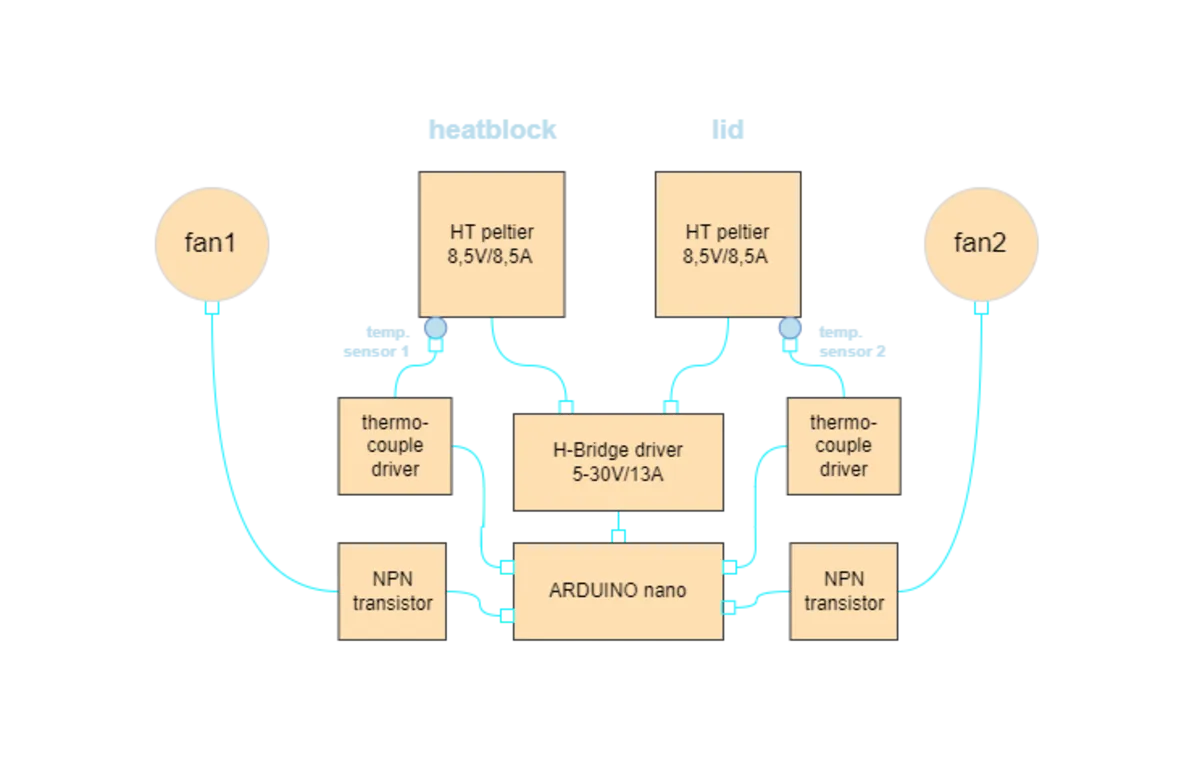
The device has two identical sections that consist of the controller itself (Arduino in this case) connected to an H-Bridge driver that forwards power to the TEC Peltier elements. The H-Bridge can reverse polarity direction so the Peltier can heat and cool the sample block when needed.
Why two identical sections, you ask? Well, because if we heated the mini vials inserted into the device only from the bottom, there would be lots of condensation due to the temperature gradient inside the vials, which from what I have read could interfere with the ongoing PCR reaction. Most commercial designs use a heated top lid for this reason, usually heated with resistance wire. (as the lid does not have so much mass to be heated up)
I will use a TEC Peltier element for both the sample block and the lid, because I don’t like the idea of the top lid lagging behind the temperature curve of the sample block.
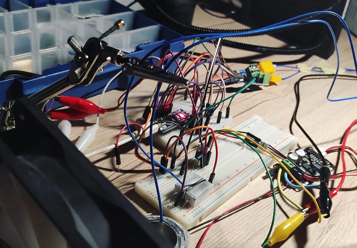
Let’s put it to the test on a breadboard version of the project. Before I made a proper sample block, I used a small chamber with water just to see how the Peltier works and to make some measurements beforehand.
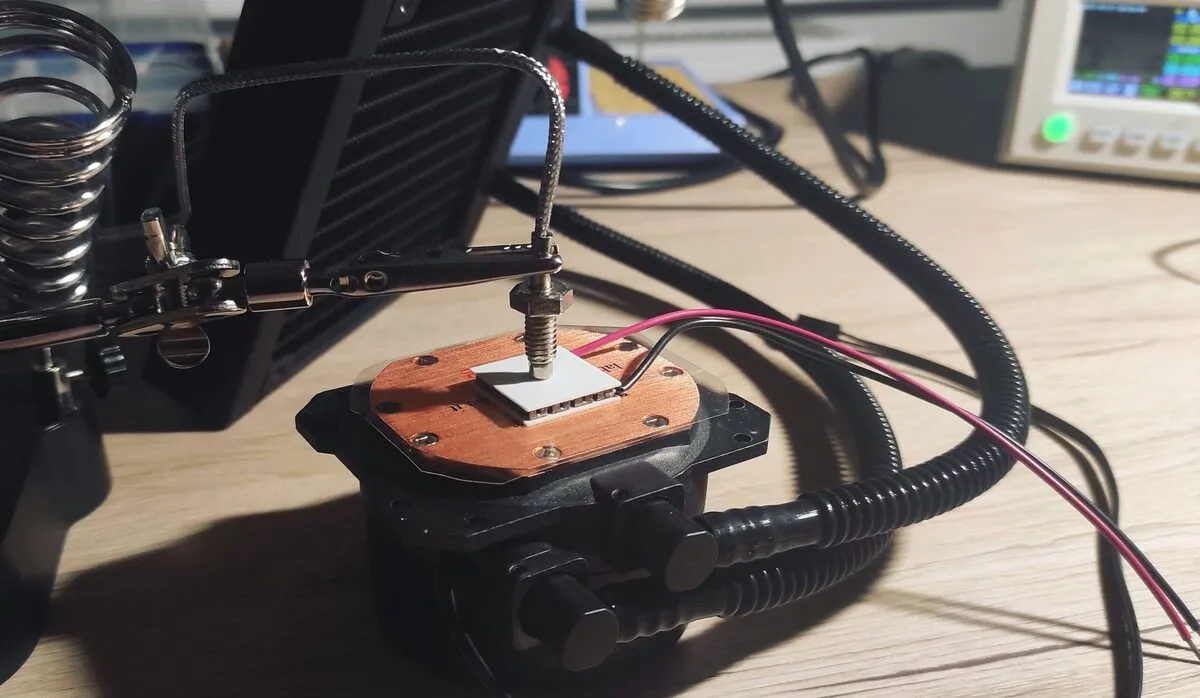
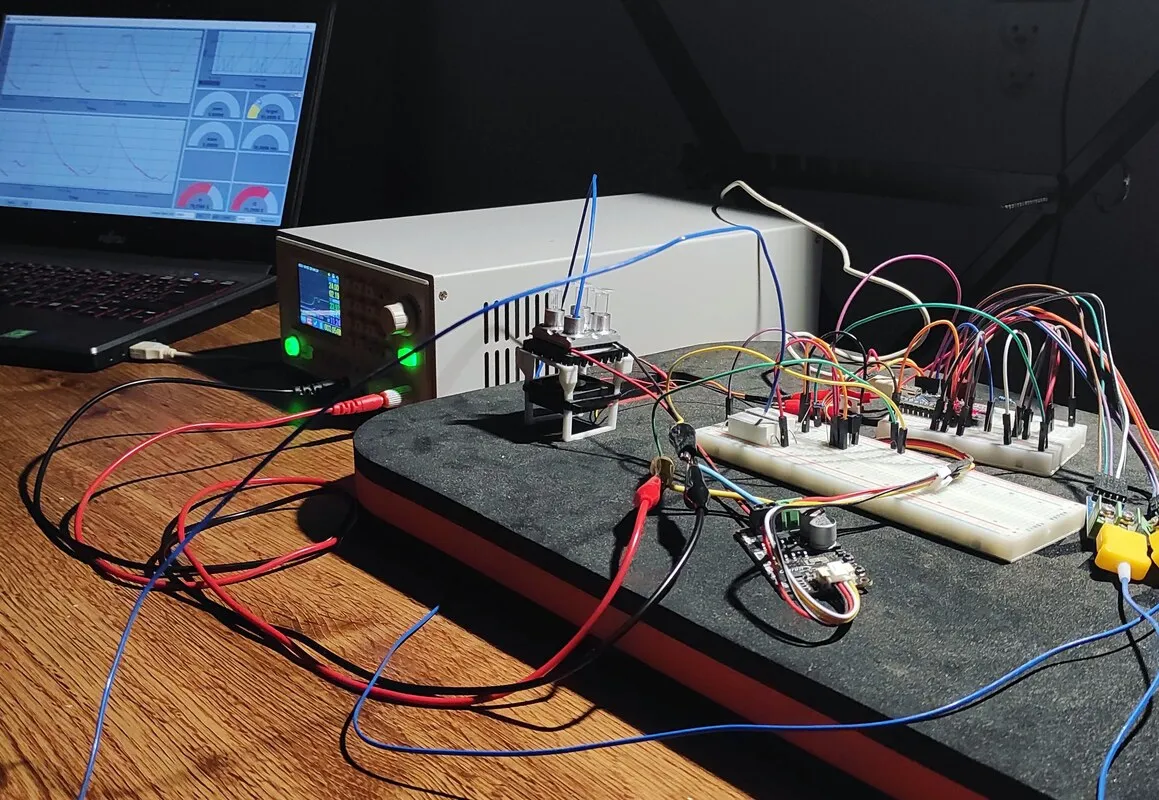
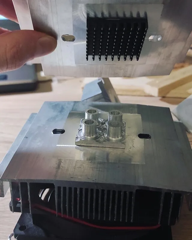
chamber & lid assembly
Finally, we can move on to mechanical construction and assemble everything together. From the last prototype test, I found out that I needed more power and a bigger cooler! The whole construction was then assembled around those coolers in a tower-like system, making it stable and sturdy.
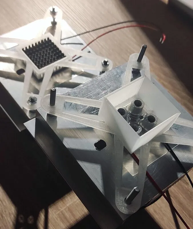
Some clamps and parts were 3D printed from ABS, which can withstand around 100 C without deforming. Initially, I was hesitant to use ABS as clamps and crimps, but after testing it beyond its temperature limit towards 200 C, I saw there was no reason not to use it. In PCR reactions, there is never a need to go above the boiling point of a sample anyway.
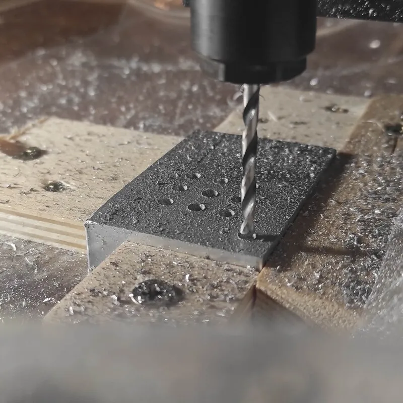
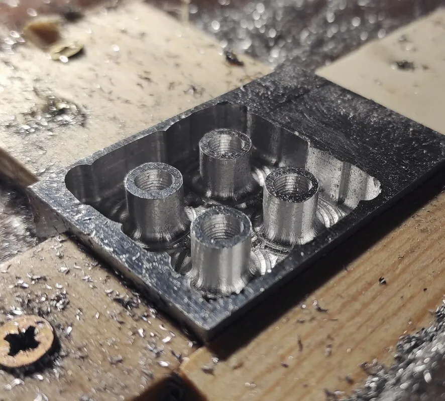
In Fusion360 I had prepared the chamber program for my CNC. This was the hardest part because it was my first time machining metal, and it did not go smoothly at all. (you can see that the chambers are elliptical, because my X axis got loose)
control parameters & software
Our thermocycler would be useless without reliable control of parameters. One option would be to re-upload the code to Arduino with different parameters every time. I considered this to make my life easier, but then after playing around with controlling Arduino via USB serial PORT, I decided to make my own software to feel better about this project. Proper design needs proper control!
What parameters, at minimum, do we need to control for each reaction?
- initial denaturation temperature + duration
- denaturation temp. + duration
- annealing temp. + duration
- extension temp. + duration
- final extension temp. + duration
- total cycle count
Making software for controlling the thermocycler was straightforward using UE4. I did not need any C++ for this and could use UnrealEngine’s native Blueprint visual scripting language.
The software consists basically only of:
serial read serial print draw graph button to start / stop / connect
the two lines you can see are the temperature of the chamber vs the lid
And some more pictures from the build: